High performance High / Low Pass Signal Filter and Vibration measuring Solutions for industry since 1965.
Kemo Ltd. founded in 1965 proudly celebrates its 60th anniversary this year, marking six decades of excellence in low-noise expertise, vibration testing, and analysis. It has proven itself as a global leader in pioneering high performance electronic filters and signal conditioning instruments. With a steadfast commitment to innovation and precision and being UKAS ISO9001:2015 certified, Kemo ensures quality and reliability, serving diverse industries with a strong global presence.
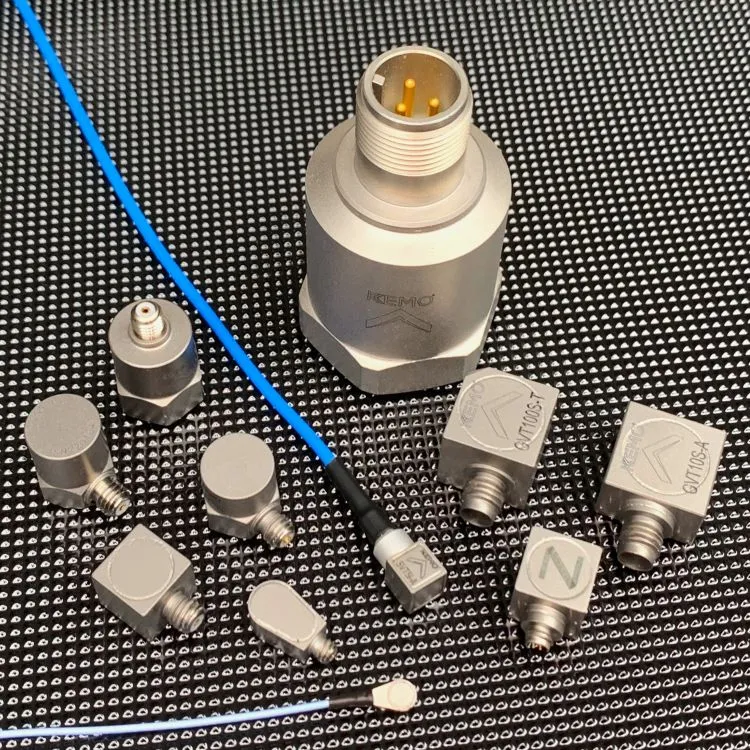
Over the last 6 decades our extensive product line has expanded to cover a wider range of vibration and acoustic based products and we now include a range piezoelectric accelerometer, coaxial cables in addition to our most popular low-pass signal filters, high pass, band pass and notch filters.
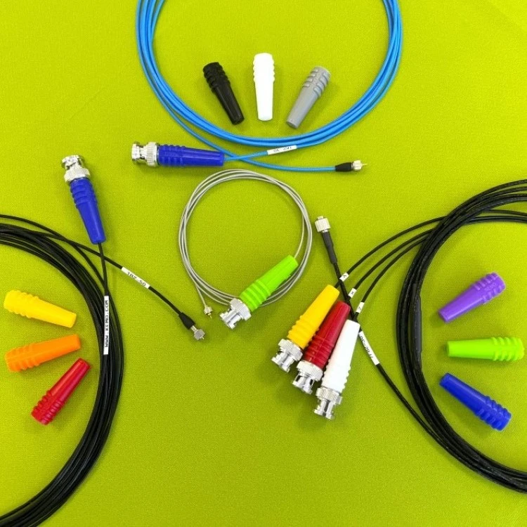
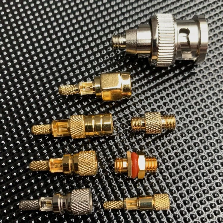
As a company dealing with customers in almost every industry sector, we have developed our technical and product support structure to ensure we can offer a more complete solution to maximise compatibility in the measurement chain and to avoid noise and errors in signal quality. Our portfolio of low-noise and instrumentation coaxial cables, connectors, joiners, and sensor mounting accessories provides the seamless integration and optimal performance across applications.
Our piezoelectric accelerometer range includes traditional charge output types for high temperature applications as well as Integrated Electronics Piezoelectric accelerometers (IEPE) which offer a simplified installation set up.
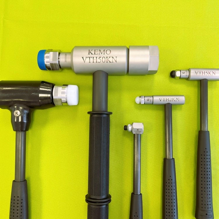
Continuing our tradition of innovation, we are excited to introduce our latest product additions, including a range of general-purpose IEPE impact hammers and handheld accelerometer calibrators. These cutting-edge solutions further underscore our commitment to pushing boundaries and delivering value to our discerning customers.
At Kemo Ltd, we remain dedicated to exploring new opportunities and enhancing our product offerings to meet the evolving needs of our customers worldwide.
Mission statement
Our mission is to promote and support high quality signal capture to ensure engineering quality is at the forefront of product design, production and operation for all our customers.
Vision statement
Our vision is to ensure the future of engineering knowledge and understanding remains at the highest level
Latest News
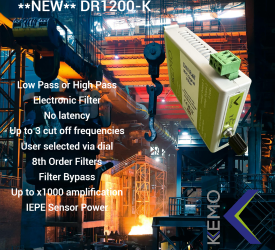
New Multi Frequency Industrial Electronic Filter
Kemo Limited have been offering bespoke solutions to its customers for over 60 years and our traditions continue today. This partnership approach has led to new product releases that meet real life...